How Resistors Work: The Unsung Heroes of Modern Electronics
Basic Brain
Electronics & Engineering • November 09, 2026
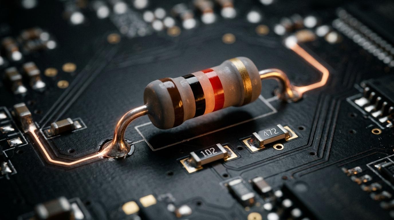
How Resistors Work: The Unsung Heroes of Modern Electronics
Whenever people think about electronics, high-tech components steal the limelight: multi-core microprocessors, OLED screens, quantum sensors, and AI accelerator chips.
Yet, if you opened up an iPhone, a Tesla motor inverter, or a NASA satellite, you would discover that the vast majority of the components soldered onto the circuit board are neither processors nor transistors.
They are resistors.
Small, silent, and often costing less than a fraction of a cent, resistors are the foundational brake pads of modern electronics. Without them, every power supply would short-circuit, LEDs would instantly explode in a flash of smoke, and digital chips would suffer catastrophic thermal failure.
In this guide, we dive into the microscopic atomic physics, governing mathematical laws, and real-world circuit design behind how resistors actually work.
1. The Physics of Resistance: Atomic Traffic Jams
To understand how a resistor controls electricity, we must look inside the atomic structure of a conductor.
In any conductive material, electrons do not move through empty space. They move through a dense, three-dimensional crystalline lattice of atomic nuclei.
When a voltage potential difference is applied across a wire, an electric field permeates the material, exerting an electrostatic force on the free valence electrons:
This force pulls the electrons forward. However, as they accelerate, they constantly collide with the vibrating atoms of the material (a phenomenon known as lattice scattering or collisions with phonons).
Every collision robs the electron of some of its forward kinetic energy, scattering it in a random direction and transferring that energy into the atomic lattice as heat (thermal vibration).
The net result is that instead of accelerating to near the speed of light, electrons crawl through a resistor at an astonishingly sluggish average drift velocity:
The Highway Analogy: If voltage is a wide-open multi-lane highway, a resistor is a narrow construction bottleneck that forces the traffic to slow down to a controlled, manageable crawl.
2. The Three Mathematical Laws of Resistance
Every electrical engineer and scientist relies on three fundamental formulas to calculate, size, and model resistors in a circuit.
Law 1: Ohm's Law (The Fundamental Triad)
Named after German physicist Georg Ohm, this equation defines the relationship between potential difference (), current flow (), and resistance ():
- If you keep the voltage constant and double the resistance, the current is cut in half.
- If you decrease resistance toward zero, the current approaches infinity—a dangerous condition known as a dead short circuit.
Law 2: The Physical Geometry Formula (Pouillet's Law)
The resistance of any physical object is determined by three geometric and physical factors:
Where:
- (rho): The intrinsic resistivity of the material (measured in ). Copper has an extremely low resistivity (), whereas carbon or nichrome has a much higher resistivity.
- : The length of the resistive conductor. Doubling the length doubles the resistance ().
- : The cross-sectional area. Doubling the thickness cuts the resistance in half ().
Law 3: Joule Heating & Power Dissipation
Because resistors convert electrical energy into heat through atomic collisions, they must be rated to safely dissipate that heat into the surrounding air:
Power () is measured in Watts (). Standard through-hole resistors are rated for () or (). If your circuit forces of power through a resistor, it will scorch, smoke, and physically crack open.
3. How Real Resistors Are Manufactured
How do manufacturers achieve an exact resistance, say precisely , in a component smaller than a grain of rice?
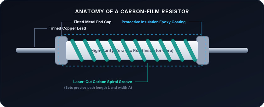
- Carbon Film Resistors: A thin film of pure carbon is deposited onto an insulating ceramic rod. A precision laser then cuts a continuous helical spiral groove through the carbon. This turns the carbon into a long, thin, coiled ribbon. By adjusting the pitch and spacing of the spiral, engineers can dial in the exact length () and width () to hit any target Ohm value.
- Metal Oxide & Wirewound: For high-power circuits (like audio amplifiers and motor controllers), a resistive wire (such as Nichrome) is tightly wrapped around a ceramic core and encased in fireproof cement.
- Surface-Mount Devices (SMD): The microscopic rectangular chips found in smartphones and laptops. They use a screen-printed metal glaze on an alumina substrate, measured in standard sizes like
0402() or0201().
4. How to Read the Resistor Color Code
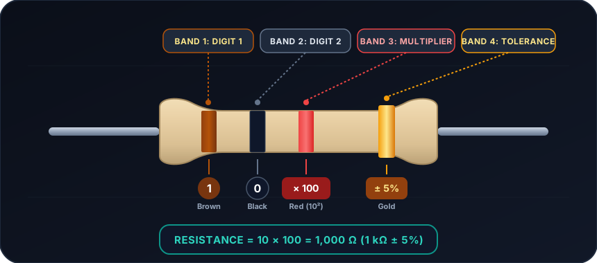
Because through-hole resistors are cylindrical and tiny, printing microscopic numbers on them would be unreadable once soldered onto a board. Instead, the industry created a standardized color-band code.
| Color Band | 1st Digit | 2nd Digit | Multiplier | Tolerance () |
|---|---|---|---|---|
| ⬛ Black | 0 | 0 | — | |
| 🟫 Brown | 1 | 1 | ||
| 🟥 Red | 2 | 2 | ||
| 🟧 Orange | 3 | 3 | — | |
| 🟨 Yellow | 4 | 4 | — | |
| 🟩 Green | 5 | 5 | ||
| 🟦 Blue | 6 | 6 | ||
| 🟪 Violet | 7 | 7 | ||
| ⬜ Gray | 8 | 8 | — | |
| ⚪ White | 9 | 9 | — | |
| 🟡 Gold | — | — | ||
| 🔘 Silver | — | — |
Practical Example:
- Band 1: Yellow (4)
- Band 2: Violet (7)
- Band 3 (Multiplier): Red ()
- Band 4 (Tolerance): Gold ()
- Value: with tolerance.
5. Four Critical Real-World Circuit Applications
1. Current Limiting for LEDs
A light-emitting diode (LED) has almost no internal resistance once it turns on. If you connect a standard power source directly across a red LED, an immense surge of current will instantly destroy the diode.
A current-limiting resistor placed in series drops the excess voltage and sets the exact current:
2. The Voltage Divider
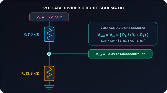
Microcontrollers like Arduino or ESP32 typically tolerate a maximum input of . If you need to read a car battery sensor, you use two resistors in series to step down the voltage proportionally:
3. Pull-Up and Pull-Down Resistors
Digital inputs are susceptible to electromagnetic noise when left disconnected (a "floating" pin). By attaching a high-value resistor (typically ) between the pin and positive voltage, you guarantee a crisp, unambiguous digital HIGH state until a button pulls it to ground.
4. RC Timing Filters
Combining a resistor with a capacitor forms an RC Filter, which cleans up noisy signals, smooths out AC ripples in power supplies, and creates precise analog time delays based on the time constant:
6. Watch the Breakdown & Visual Demonstrations
Seeing current limiting and voltage division visualized with animated current flow brings these principles to life. Watch this clear engineering breakdown:
Explore More Engineering on Basic Brain
For animated breakdowns of engines, semiconductors, electricity, and the mechanical machines that shape our world, check out:
- 🎥 Basic Brain on YouTube (@basicbraincut) — Visual explorations into electronics, physics, mechanics, and history.
7. Summary & Key Takeaways
- Resistance is atomic friction: Free electrons collide with lattice ions, converting kinetic energy into thermal heat and slowing down drift velocity.
- Ohm's Law is universal: Current is directly proportional to voltage and inversely proportional to resistance ().
- Geometry controls resistance: Longer paths increase resistance; wider cross-sections decrease it ().
- Resistors must handle the heat: Always calculate Joule dissipation () so you don't exceed your component's wattage rating.
- They enable precision control: From voltage dividers and current limiters to pull-up resistors and RC filters, resistors are the foundational controllers of modern circuits.
Written & curated for the Basic Brain engineering library. Have questions about resistor circuits or circuit math? Let's discuss in the comments below!